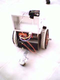
The basic robot uses a pair of motors, one on the left and one on the right, and is driven like a tank (also called a unicycle in the literature). That is, to go straight forward, both motors are go forward at the same speed. To turn, one side or the other is turned faster. This is a very popular robot scheme for a lot of reasons. You've got to have two motors if you need two degrees of freedom (i.e. you want to do anything other than drive in a straight line). Either you do the unicycle thing, or the 1 traction, 1 steering scheme, or something else (Take a look at the Gyrover), which generally reduces to one of these. It just seems that it is easiest to take two identical motors and control them identically, etc. I've used this on a number of motion platforms over the years.
It turns out, though, that controlling one of these, in an analytical sense, is pretty tricky, because it can't be linearized. That is, your (x,y) position at some time, t, is a function of sines and cosines, etc., and being transcendental functions, they can't be exactly represented by any finite polynomial. This property is called non-holonomy. If you need to control your exact path, it makes motion planning very difficult. As a practical matter though, where you just want to go from point A to point B, over uneven terrain, and you are willing to tolerate some variations, there are a lot of heuristic navigation schemes (i.e. just keep driving towards your goal, adjusting all the time, rather than planning the whole trip in advance).
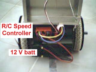
My first implementation was to get a couple of radio controlled car motor speed controllers (Called ESCs (electronic speed controllers), they run around $150 each for ones that go in reverse, etc.) and hook them up to the motors. I then used a standard R/C transmitter/receiver to drive the thing around, putting each motor on one joystick. The RC controllers aren't rated for 24V, so I just hooked them up to 12V. This was pretty useful and informative as I drove the thing around the house and yard. I learned that any sort of "odometry" was doomed because of wheel slip, and that likewise, controlling direction in an open loop fashion by controlling motor current or pulsewidth was also doomed for similar reasons.
|
|
I figured at that time that I would just write some code for the Rabbit2000 to generate the RC pwm signals and I'd be done with it. It turns out, though, that this is a real pain to implement on the Rabbit, unless that's ALL you'd like to do (of course, one could argue that tying up a $20 Rabbit with this is a reasonable proposition). I then contemplated hooking up a PIC to generate the PWM signals, driving the PIC from the Rabbit. However, the driving tests that doomed the RC controller was the fact that 12V just wasn't enough juice for the motors, which were really designed to run off 24V. The robot moved fast enough (around 1 m/sec) on level ground, but going up hill (6% grade) it slowed a lot and over bumps it was pretty iffy. Consultation with some of my acquaintances who are into the whole RC thing about the possibility of running the ESC's off 24 V weren't hopeful: they thought the pass devices would work, but that the 5V regulator that runs the logic would burn up.
| On to plan B: I had built some VMOSFET H-bridges about 15 years ago for "Roger", to drive just these motors with 24V. They are (IRF530 and IRF9540) optoisolated, and were driven by a wirewrapped Z80 based controller with an RS232 interface to give PWM commands. A real simple program in the EPROM is used to program some 8253 timers to generate the waveforms. The real problem was that the Z80 board isn't exactly low power, and, of course, technology has advanced a bit in the last 15 years. Maybe I could program the rabbit to drive the Hbridges, or, alternately, program the PIC. | 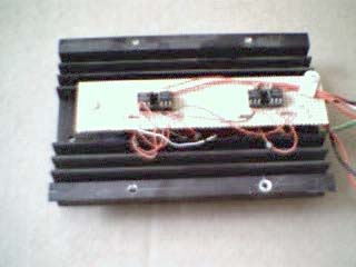 |
A little contemplation of the time it would take to do this, though, inspired me to consider a third plan: buy a modern dual motor speed controller from Vantec in Nipomo,CA. I have used their products at Reel EFX, and they are tough, well designed, and not too expensive. A suitable computer controlled controller (CDFR series) would set me back only about $250 (less than the pair of RC ESC's, but those were bought on an impulse.. gotta have it now, tonight...), and they usually deliver in a few days. A call to Vantec resulted in the unhappy news that due to the huge popularity of BattleBots (and the like), he's so busy that the delivery time would be something like 8 weeks. So much for impulse buying a speed controller. Back to plan B, and if I don't get it done by June, and Vantec's less busy, I may still buy their box.
Here it is, the last week of May, and I still haven't done much on the PIC, and a call to Vantec gets the happy news that the delivery time is down to a week, so I order a pair of the CDFR22 units (24V, 20A avg, 60A pk). I'll save the PIC stuff for later (design info). Why two? I've been intrigued recently by the multiple degree of freedom robot combining two "unicycle" bases with a compliant bar as described by Borenstein. Now, of course, I need to get another set of motors (hah...like I could duplicate them) or, at the least, a set of 4 reasonably matched drive motors.
Maybe I'll leave the R/C ESCs hooked up to the base I've got and turn it into a sphericle? Gotta find that plastic ball.